EPA TO-15A Canister Sampling System Requirements
EPA TO-15A Canister Sampling System Requirements
By Dan Cardin
Although this article relays the requirements found in US EPA Method TO-15A, the rationale, theory, or background presented for these requirements expressed herein are based on the authors 30+ years of working with hundreds of canister laboratories world-wide, and through the inhouse research conducted at Entech Instruments, and are not necessarily found in the method and in no way represent an endorsement by the EPA. This article provides insight from a company specializing in canister sampling and analysis to help others who are endeavoring to achieve optimal performance of their methods and techniques.
In this 3rd installment of our article series covering US EPA Method TO-15A, we will be addressing the updated QA requirements for canister sampling trains, including new flow calibration, blank testing, and recovery validation as well as the approaches you can use to meet these more robust and challenging method specifications. This article will focus on the use of passive samplers that rely on the vacuum inside of the canister to create the driving force that fills the canister over a pre-determined sampling integration period of an hour, a day, or up to 1 month, while maintaining a constant flow rate over the entire duration . This article will not address the more difficult task of calibrating pump based systems, which, in order to reduce contaminants outgassing from the pump and to limit residence time in the sampling system, usually draw far more sample than is actually delivered to the canister. In some cases, these pumps are downstream of the point where sample is diverted into the canister, and simply serve to get the sample from the inlet line outside, to a point of close proximity to the fill rate metering system. However, in both the case where the sample goes through the pump prior to reaching the canister, or the canister draws from the rapid flow of air just prior to the pump, the consumption of calibration gas would be far greater than when sampling directly into the canister through a passive flow controller. High consumption rates would exhaust the high-pressure cylinder standard mix very quickly, making this traditional source of certified standard too expensive. About the only approach that may work for pump based systems to validate target compound recovery (100% +-20%) would be to use a permeation system that could deliver the sample consistently for days, although these are generally limited to mixtures with far fewer compounds than in the TO-15A list, and certification of these systems may present a problem. In any case, we will be looking today at the classical time integrated sampling of 24 hours using the vacuum of the canister to draw the sample or standard through the sample train and into the canister.
Although the original TO-15 did address the need to verify target compound recovery through canister sample trains, these were more suggestions than requirements. In fact, the EPA considers the original TO-15 to be a compendium method….
From Wikipedia…
A compendium (plural: compendia) is a concise collection of information pertaining to a body of knowledge. A compendium may summarize a larger work. … The word compendium arrives from the Latin word “compenso”, meaning “to weigh together or balance”.
However, TO-15A is no longer a compendium method, but a full EPA method. Perhaps it is not as rigid as more regulatory methods, but it is also no longer just a summary of a larger body of knowledge. Therefore, before a lab can state they are compliant with the new TO-15A, any deviations must be either approved by the EPA, or at least any changes must be noted by the laboratory as alterations to the method.
Here is the basic list of the new requirements for time integrated, time weighted sampling:
- Sampling trains must be calibrated and demonstrated to achieve a constant flow rate, with sampling stopping while the canister is still 3-6” Hg below local atmospheric pressure to ensure a constant sampling rate over the entire sampling period.
- Sample trains must be shown to yield no more than a 20 ppt increase to the blank level of each target compound.
- Sample trains must be shown to recover from 80% to 120% of each target compound, relative to the challenge mix.
Each one of these will now be discussed in detail.
I. Sample Train Flow Calibration
Based on the type of sampler being used, the calibration device can be one of several styles of flow meters, but the attachment of the flow meter must not have any affect on the flow rate of the sample train. In general, flow meters that are often used to calibrate canister sampling flow rates require occasional recalibration because they are based on relative response of sensors and amplifiers which may drift over time. To eliminate this as a variable, Entech has chosen to use a physical law that has been well accepted for a few hundred years, that will not drift or change over time. The Ideal Gas Law was discovered by physicist-engineer Benoît Paul Émile Clapeyron in 1834, so nearly 200 years ago, and uses the non-changing equation PV=nRT to relate number of moles of a gas to its temperature, pressure, and volume. This equation holds very well for virtually all gases at 1 atm pressure and below, except for HF that appears to have enough hydrogen bonding even in the gas phase to require the non-ideal gas law to express the relationship between the aforementioned parameters. For air, the ideal gas law holds to several atmospheres of pressure, and certainly through the vacuum range, so we can use it to determine flow rates. If we rearrange the equation and solve for moles of air, then:
n=PV/RT
If we fill up a reservoir of known volume using a flow of gas where we can measure the pressure at any point in the filling of the reservoir, then we can look at the change in the number of moles in that reservoir, and since 1 mole occupies 24.4L at 25 deg C, we can then convert that to liters transferred during that time period. The first derivative of volume is the flow rate, and we can easily express that in cc/min. Therefore, using a pressure sensor that can be easily adjusted to read 0-0.1 psia under a strong vacuum (zero adjust), while also confirming the accurate reading of the local laboratory atmospheric pressure (gain adjust), we can perform a calibration of this sensor each time it is to be used.
Entech introduced a calibration system several years ago called The Flow Professor that attaches to the CS1200Ex flow controller to allow leak checks and automated calibrations. Rather than filling up a 6L canister and measuring the change in pressure over time, which would take a long time, especially for longer sampling times (1-4 weeks), the Flow Professor uses a volume of 4.3cc downstream of the flow controller to allow pressure changes to occur more quickly so that flow rates could be determined faster and more accurately. That is, for the typical flow rate of about 3.5cc/min to fill a 6L can in 24 hours, the pressure in a 4.3cc reservoir will change a lot faster than in a 6000cc reservoir (6L canister volume). In fact, a 4.3cc reservoir is small enough to allow much lower flow rates to be easily calibrated, down to as low as 0.1cc/min, allowing a 6L canister to be filled at a consistent rate over the course of a month.
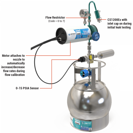
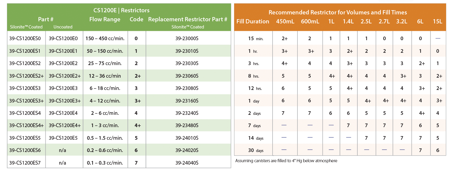
Figure 1 shows the Flow Professor attached to a CS1200Ex flow controller. Like most mechanical flow controllers, an internal nozzle can be adjusted to provide approximately a 3x change in flow rate, by changing the internal pressure of the regulator to be about 1-3” Hg below the inlet pressure, which is typically atmospheric pressure. This allows the flow into the canister to remain constant until the pressure of the canister is also within 1-3” Hg of atmospheric pressure, after which the flow will begin to slow down when the canister can no longer maintain the 1-3” Hg differential across the inlet restrictor. The CS1200Ex uses a larger diaphragm than other canister flow controllers, which allows it to be more responsive, and more stable when operating at low pressure differentials (1-2” Hg). A range of 3x control is not very much, but the CS1200Ex can still cover the entire range of desired flow rate (0.1-200cc/min) simply by changing the inlet restrictor. Entech offers 10 different restrictors (Figure 2 below) to allow the flow controller to be ready for final calibration within the range allowed by each restrictor. For a 24 hour fill rate into a 6L canister, a #4 restrictor is used, which allows flows from about 2.5-7.5cc/min, which includes the target flow rate of 3.5cc/min to fill a 6L can in 24 hours.
Figure 2. CS1200Ex Restrictor & Fill Time Guide
The Flow Professor can not only detect the flow rate, but it can also change it, by using its internal motor to change the distance of the control nozzle away from the diaphragm. The further the nozzle is away from the diaphragm, the greater the pressure difference required to deflect the diaphragm, and the greater the pressure drop across the front restrictor, and therefore the faster the flow rate. The Flow Professor can evacuate the 4.3cc outlet volume, measure the pressure change rates as that 4.3cc volume pressurizes (CS1200E flow rate), and then adjust the nozzle in or out to obtain the target flow rate. All this occurs automatically based on the method parameters on the WIN10 computer running the Flow Professor software. If there is a problem with the flow controller, such as a leak or a restrictor issue that prevents the flow controller from being calibrated at the required flow rate, the software will indicate this. Generally, tightening a fitting or changing a restrictor will resolve most issues.
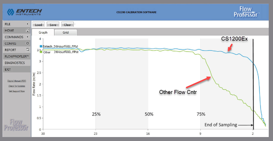
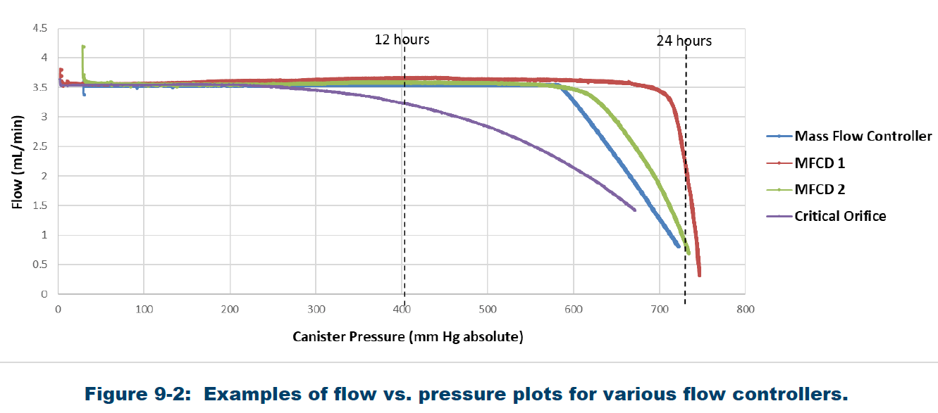
TO-15A not only requires that the flow rate be calibrated, but that the rates remain constant through the entire fill process. This turns out to be easy with the Flow Professor. Using the 4.3cc internal volume, a “flow rate vs remaining vacuum” profile can be generated automatically in under 2 minutes when sampling at 3.5cc/min, the flow rate needed to fill a 6L canister in 24 hours. Figure 3 shows the flow rate graph generated by the Flow Professor, while Figure 4 shows the flow rate graph from TO-15A. The flow rate vs pressure curve must be obtained for each sample train to show that the flow remains constant throughout the sampling period. Since TO-15A suggests a 3-6” Hg final target vacuum in the canister after sampling, the flow rate should remain constant down to 3” Hg, which the CS1200E easily achieves as evidenced from the flow vs vacuum curve in Figure 3. Once a flow controller has been demonstrated to meet this requirement, further flow vs vacuum curves need not be generated, unless any part of the flow controller is changed. The Flow Professor automates this process, so Entech suggests allowing the Flow Professor to create this curve every time the flow controller is calibrated.
II. Validating Cleanliness of the Sample Train
TO-15A also requires validating the sample train for cleanliness, and for proper target compound recovery. Both the blank challenge gas and the calibration gas must be at 40-50% relative humidity, and at least the blank testing must be performed using zero air, not Nitrogen. Also, to be a valid test, the flow rate through the sample train must be nearly the same as the flow rate in which the sample train will be used, so for a 24 hour, 6L can sampling, the flow should be about 3.5cc/min. The problem with this requirement is that canister samplers require that the inlet gas be at atmospheric pressure, which is a difficult pressure at which to maintain a blank or calibration gas. Even operating at just 1 psig above atmospheric pressure, the flow rate can double through the sample train, so this simply is not an option.
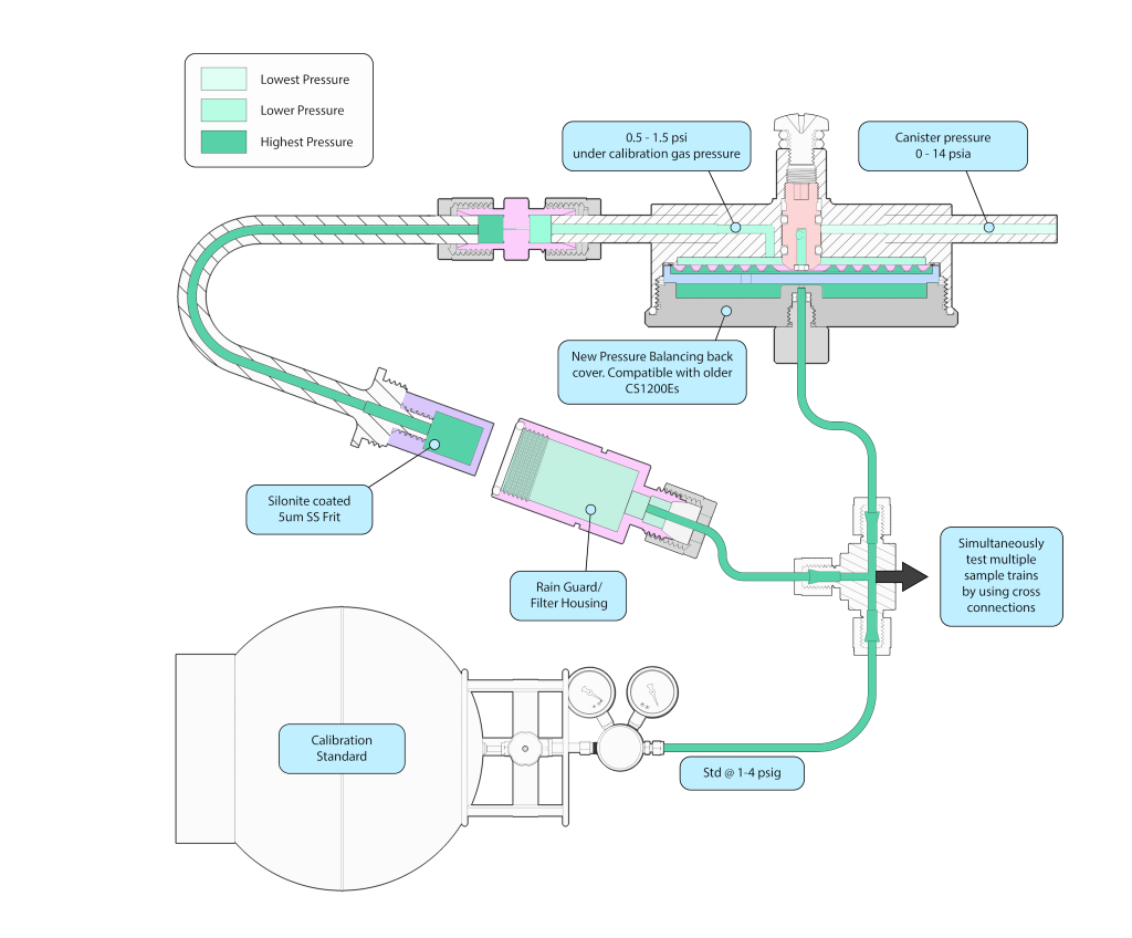
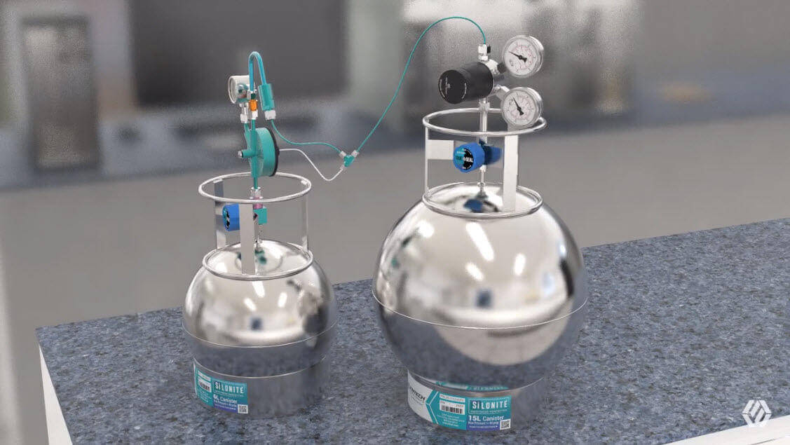
Figure 5 shows a new patent pending approach that allows the CS1200E to be connected to a pressure regulated standard or humidified zero air mixture at 1-4 psig. A newly designed CS1200Ex back cover (watch animation ‘insert link) allows the calibration standard or a humidified blank to connect to the back side of the flow controlling diaphragm, which compensates for the higher pressure at the inlet, allowing flow rates to be nearly the same as when sampling at atmospheric pressure. At 2-3 psig pressure, the flow through the CS1200E will be about 4cc/min instead of 3.5cc/min. To compensate for this, the Flow Professor can first calibrate the flow rate to 3.0cc/min, resulting in a perfect 3.5cc/min flow during blank or recovery testing. Entech recommends using short, Silonite coated 1/8” stainless tubing to connect the 1-4 psig standard to the sample train and canister. By using a cross instead of the tee shown in Figure 5, the calibration gas can be directed to a second, third, fourth, or fifth sample train/canister combination to allow many systems to be blank or recovery tested at the same time. As mentioned before, for blank testing, the sample train must not increase the level of TO-15A analytes by more than 20 ppt. Therefore, the blank canister can be analyzed and compared to the canisters that were filled through their respective sample trains to verify that less than a 20 ppt increase occurred. Figures 6 & 7 (animation) depict the actual bench top arrangement of the testing equipment.
Upgrade your existing CS1200E’s by ordering part # 39-CS1200-15A. One kit is needed for each CS1200E
You’ll also need the Equilibrating Fitting (#01-39-CS1200-46) when setting up the validation test. One fitting per CS1200E that you have simultaneously setup for validation. For example, if you plan to validate at most 5 units at a time, then just 5 fittings are needed.
Figure 7 (Animation). New CS1200Ex Feature for Sample Train Validation
III. Recovery Testing of Sample Train
For testing target compound recovery, the test mix must be in the range of 0.1 to 0.5 PPBv, and no higher. TO-15A suggests using the concentration range expected during sampling, but labs have no idea what this will be, so anything in the 0.1-0.5PPBv range should be fine. The idea is to evaluate the presence of active sites without covering them up by artificially exposing them to high target compound levels. Using the 4700, a 0.4 PPB standard can be made in a 15L canister by first making a 20 PPB standard in a 6L can, and then further reducing the concentration of that standard down to 0.4 PPBv in a second dilution step. Considering the 4700 uses 3-10 times less standard than dynamic dilution systems, and that the new pressure balancing requires no standard to be wasted, unlike other flow controllers that require excess standard to flow past the flow controller inlet at atmospheric pressure, the new recovery testing requirements of TO-15A can easily be done without obtaining any more standard cylinders than have been required by labs in the past. That is, the certification period will pass faster than the cylinders will be used up, even when testing large numbers of sample trains. This will result in huge savings to labs as these new QA requirements go into effect.
The blank and recovery testing of sample trains is to be done for initial use, or whenever the sample train has been exposed to a high concentration sample or damaging matrix, or when part of the sample train must be exchanged. TO-15A states that blank testing should as a minimum occur annually. Although an assumption can be made that a filter can be changed without going through these tests again, that may not be a great assumption. Entech produced application notes in 1999 and 2014 that demonstrated great recoveries of the heavy TO-14/TO-15 compounds with Silonite coated SS inlet filters, but for non-coated stainless filters Hexachlorobutadiene and Trichlorobenzene recoveries were below 60%. These filters have a lot of internal surface area, and probably more than the rest of the flow controller combined. Maximizing the inertness of these inlet filters is critical, both for recovery and for rapid cleanup. TO-15A states that recovery and blank testing should be repeated after cleaning, but they probably mean when disassembling and cleaning each part in a sonicator, for example, not after cleaning by purging the flow controllers with a gas, as in a canister cleaning system.
Finally, can older CS1200Es from Entech perform the new pressure balancing, to allow operation at 1-4 psig inlet pressures? The answer is yes, at least for CS1200E flow controllers purchased in the past 5-6 years. Simply by obtaining some of the new back covers and tubing adapters (click here to request a quote), the old covers can be removed and replaced with the new back covers, the test can be performed, and then the old back covers can be placed back onto the CS1200E. The back cover is not part of the sample flow path during normal operations, so for actual field use after the blank and recovery testing has concluded, the original back diaphragm covers will work fine.
Thank you for hanging in there to the end of this article. Entech remains dedicated to providing our customers with all the tools needed to meet the needs of canister monitoring applications, including the increased demands of method TO-15A. If you have any questions or feedback for us, we’d love to hear from you. We are here to help, and to make your transition to TO-15A less stressful. In the end, we believe the new method QA requirements will allow the canister technique to finally reach its potential of being one of the best EPA methods ever, for any matrix, for both accuracy and reliability.

